
12 & 24 Volt | Part Number: 0481
(Supersedes Part No. 0445)
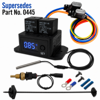
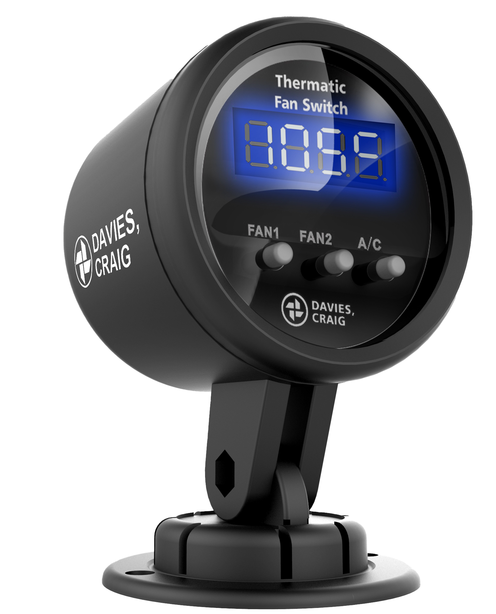
Upgrade your cooling control with the latest GEN II Digital Thermatic® Fan Switch which includes the ¼" NPT Sensor redesigned for improved usability, durability, and performance. Built for precision temperature management, this next-generation controller delivers smarter fan operation and enhanced installation flexibility.
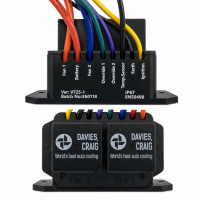
(Refer to installation diagrams and wiring layout shown on page 3 of the instructions for full setup guidance.)
The GEN II isn’t just an update—it’s a complete usability and performance improvement over Part No. 0445. With smarter control, faster response, improved installation design, and direct coolant sensing capability, it delivers everything needed for modern cooling systems.
|
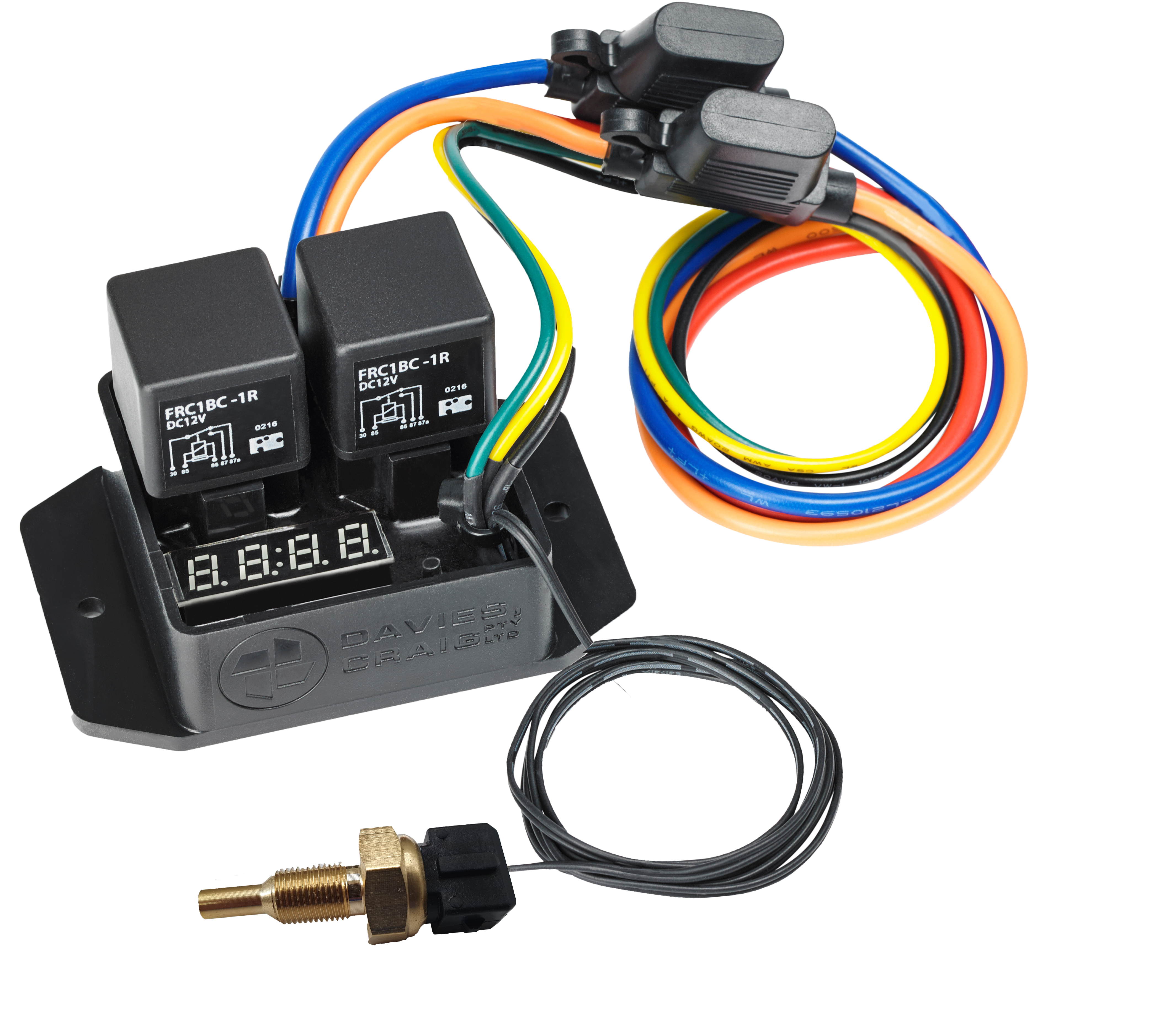
KIT CONTENTS |
|
|
DESCRIPTION |
UNITS |
| Digital Fan Switch GEN II (IP67) |
1 |
| Thermal Sensor Probe | 1 |
| ¼" NPT Sensor | 1 |
| Mounting Kit for Thermal Sensor Probe | 1 |
| Red 6mm Ring Terminal | 1 |
| Blue 6mm Ring Terminal | 1 |
| Blue Wire Joiner | 2 |
| Self Tap Screw | 2 |
| Instructions | 1 |
| Specs | 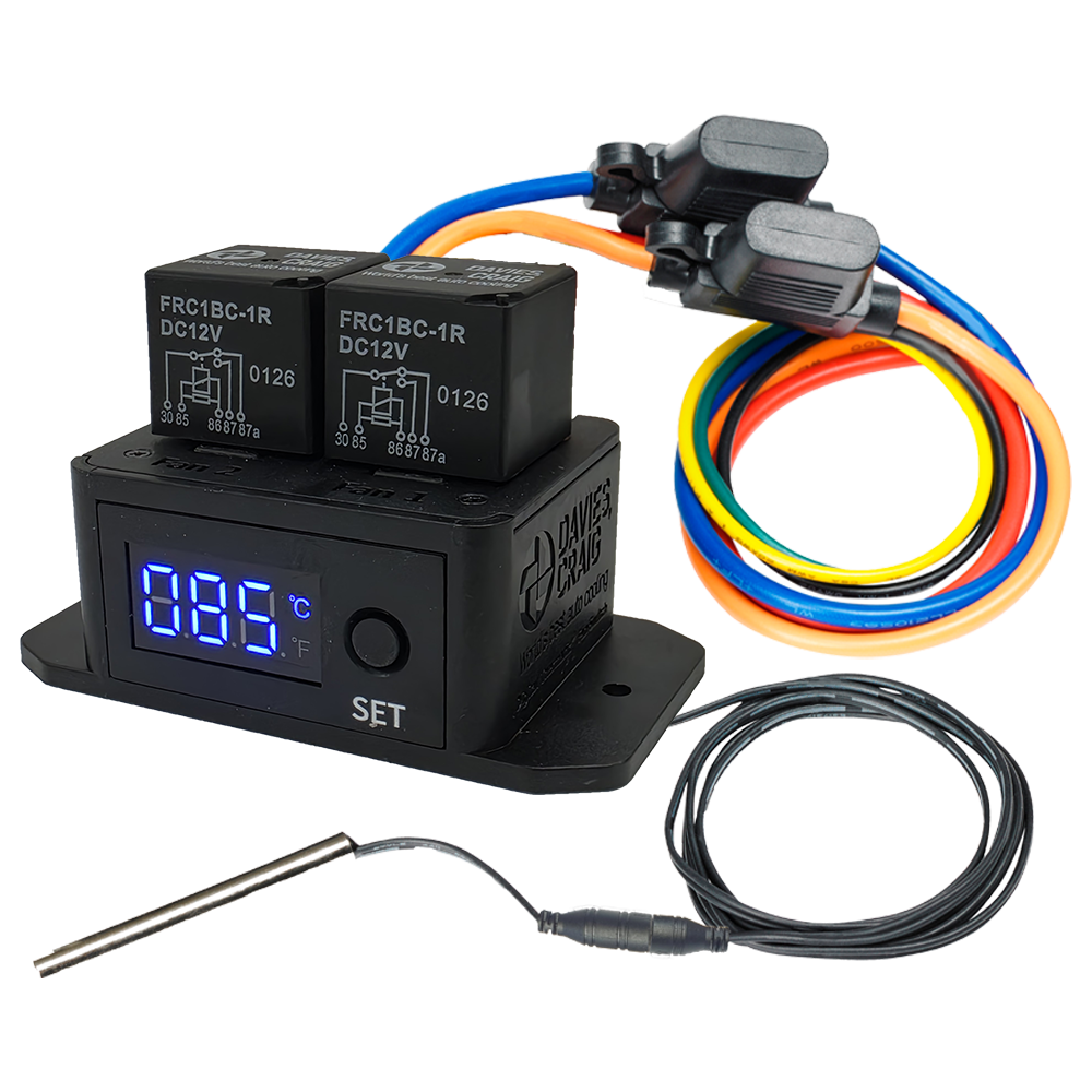 |
 |
 |
 |
 |
 |
|
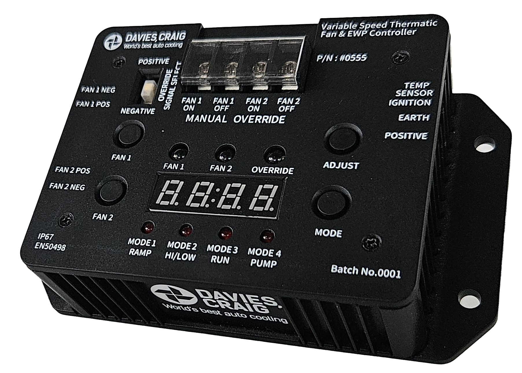
| Part #0480 | Part #0444 | Part #0401 | Part #0500 | Part #0555 | Part #0550 | Part #8003 | |
| Supersedes Part No. |
#0444, #0445, #0448 #0435, #0438 |
N/A |
N/A | N/A | N/A | N/A | #8002, #8102 |
| Sales Variation |
#0481, #0482, #0483, #0485, #0488 |
#0445, #0448 #0435, #0438 |
#0400, #0404 | #0501 | #0556 | #0551 | #8103 |
| Operating Voltage | 12 & 24 Volt | 12 & 24 Volt | 12 & 24 Volt | 12 & 24 Volt | 12 & 24 Volt | 12 & 24 Volt | 12 & 24 Volt |
| Maximum Current | 40 Amps | 40 Amps | 20 Amps | 40 Amps | 40 Amps | N/A | 12 Amps EWP Only |
| Fan Application | MAX 30A Each | MAX 30A Each | Relay Switching Current MAX 15A | All DCPL Fans, EWPs & EBPs | All brushed DCPL Fans, EWPs | All Brushless DCPL Fans, EWPs | All DCPL Fans, EWPs |
| Speed | Single Speed | Single Speed | Single Speed | Single Speed | Variable Speed | Variable Speed | Single speed Fan & Variable EWP |
| Single Fan Control | Brushed FAN only | Brushless FAN only | |||||
| Duel Fan Control | Wiring Dependant | Brushled FANs only | Brushless FANs only | ||||
| EWP control | ON / OFF ONLY (USE 8003) | ON / OFF ONLY (USE 8003) | ON / OFF ONLY (USE 8003) | ON / OFF ONLY (USE 8003) | Brushed EWPs only | Brushless EWPs only | |
| EBP control | ON / OFF ONLY | ON / OFF ONLY | ON / OFF ONLY | ON / OFF ONLY | |||
| EWP/EBP and Fan control | Wiring Dependant | EWP and Fans only | |||||
| Duel Fan Start-Up Delay | 5 Seconds | 10 Seconds | Independent set Temperature | 4 independent Operating modes | 5 independent Operating modes | Independent set Temperature | |
| Manual Override - Turn On | 2 Fan Override Wires | use #0404 | Selectable Fan Override | 2 Fan Override Wires | 2 Fan Override Wires | 2 Fan + 1 EWP Override Wire | |
| Manual Override - Turn off | 2 Fan Override Wires | 2 Fan Override Wires | |||||
| Manual Override - Voltage Selection | |||||||
| °C to °F Change | No temperature units | ||||||
| Temperature Setting Range |
5°C To 110°C (41°F To 230°F) |
40°C To 110°C (104°F To 230°F) | 40°C To 100°C (104°F To 212°F) | 5°C To 110°C (41°F To 230°F) | 5°C To 110°C (41°F To 230°F) | 5°C To 110°C (41°F To 230°F) | 40°C To 110°C (104°F To 230°F) |
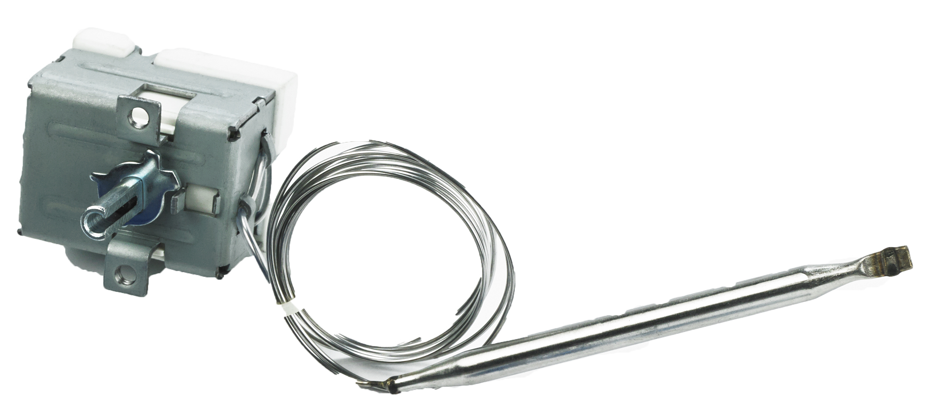
| Temperature Setting Method | Push Button | Push Button | Turn Knob | Push Button | Push Button | Push Button | Push Button |
| Coolant Temperature Detection | Requires #0409 or #0465 | Requires #0409 or #0465 | Requires #0409 or #0465 | ||||
| Air Temperature Detection | |||||||
| Transmission Temperature Detection | Fluid measurment Requires #0465 | Ambient temperature only | Fluid measurment Requires #0465 | ||||
| Display Type | Led Segment | Led Segment | Led Segment | Led Segment + Status LEDs | Led Segment + Status LEDs | Colour LCD | |
| Temperature Display | |||||||
| Sensor Fault Display | |||||||
| Fan Operation Indicator | EWP and Fan1 and FAN2 | ||||||
| Over Temperature Warning | |||||||
| Audible alarm | |||||||
| Display dimmer | |||||||
| Mounting position | Engine bay | Engine bay | Engine bay | Vehicle Cabin | Engine bay | Engine bay | Vehicle Cabin |
| Mounting options | Built in Mounting holes | Built in Mounting holes | Bracket supplied | Universal 52mm gauge | Built in Mounting holes | Built in Mounting holes | Verious Mounting Options supplied |


