Distributors Login
Forgot Password
Sign Up
Items: 0
Total: AUD 0.00
View Cart
Distributors Login
Menu
Toggle navigation
home
About Us
Product Info
Electric Water Pumps
Electric Booster Pumps
Thermatic® Electric Fans
Switches & Controllers Fan & EWP®
Transmission / Engine Oil Coolers
Marine
TyreGuard & TPMS
Fan Clutches
Spare Parts
Testimonials
Buy Now
Distributors
Fan Selection Guide
Marine
VIDEO
Blog
Support
Contact Us
Catalogues
Instructions
FAQ
Warranty
home
About Us
Product Info
Electric Water Pumps
Thermatic® Electric Fans
Switches & Controllers Fan & EWP®
Transmission / Engine Oil Coolers
TyreGuard & TPMS
Fan Clutches
Spare Parts
Testimonials
Buy Now
Distributors
Fan Selection Guide
Marine
VIDEO
Blog
Support
Contact Us
Catalogues
Instructions
Faq
Warranty
Product Search
Select Category
ELECTRIC WATER PUMPS (EWP®)
ELECTRIC WATER PUMPS (EWP®) / Electric Water Pump 12Volt
ELECTRIC WATER PUMPS (EWP®) / Electric Water Pump 24Volt
ELECTRIC WATER PUMPS (EWP®) / Brushless Electric Water Pumps
ELECTRIC WATER PUMPS (EWP®) / EWP BLOCK ADAPTERS
ELECTRIC BOOSTER PUMPS (EBP)
THERMATIC® ELECTRIC FANS
THERMATIC® ELECTRIC FANS / 12 Volt Electric Fans
THERMATIC® ELECTRIC FANS / 24 Volt Electric Fans
THERMATIC® ELECTRIC FANS / Brushless Electric Fans
SWITCHES FAN & CONTROLLERS EWP
TRANSMISSION / ENGINE OIL COOLERS
TYREGUARD / TPMS
SPARE PARTS & ACCESSORIES
Home
Products
Products
8" Thermatic® Electric Fan (12V) (#0135)
AUD 87.15
(Ex. GST)
Add to Cart
View Product
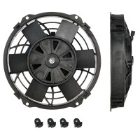
Brushless 8" Thermatic® Electric Fan (12V) (#0121)
AUD 299.00
(Ex. GST)
Add to Cart
View Product
8" Thermatic® Electric Fan (24V) (#0136)
AUD 102.90
(Ex. GST)
Add to Cart
View Product
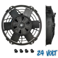
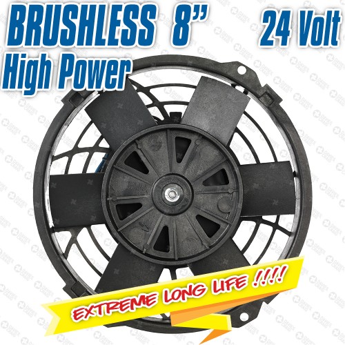
Brushless 8" Thermatic® Electric Fan (24V) (#0122)
AUD 299.00
(Ex. GST)
Add to Cart
View Product
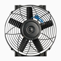
9" Thermatic® Electric Fan (12V) (#0160)
AUD 87.15
(Ex. GST)
Add to Cart
View Product
Brushless 9" Thermatic® Electric Fan (12V) (#0123)
AUD 299.00
(Ex. GST)
Add to Cart
View Product
9" Thermatic® Electric Fan (24V) (#0161)
AUD 102.90
(Ex. GST)
Add to Cart
View Product
Brushless 9" Thermatic® Electric Fan (24V) (#0124)
AUD 299.00
(Ex. GST)
Add to Cart
View Product
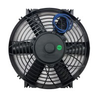
10" Slimline Thermatic® Electric Fan (12V) (#0147)
AUD 87.15
(Ex. GST)
Add to Cart
View Product
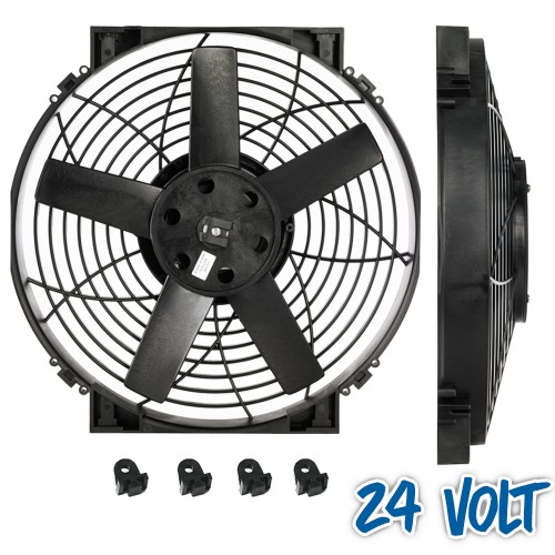
10" Slimline Thermatic® Electric Fan (24V) (#0148)
AUD 102.90
(Ex. GST)
Add to Cart
View Product
Featured
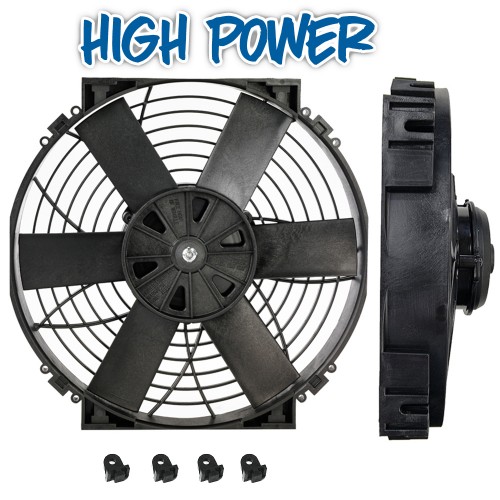
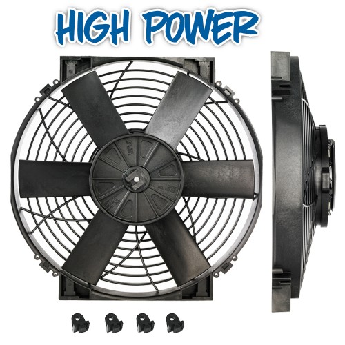
10" High Power Thermatic® Electric Fan (12V) (#0150)
AUD 163.00
(Ex. GST)
Add to Cart
View Product
Brushless 10" High Power Thermatic® Electric Fan (12V) (#0125)
AUD 335.00
(Ex. GST)
Add to Cart
View Product
Featured
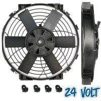
10" High Power Thermatic® Electric Fan (24V) (#0151)
AUD 163.00
(Ex. GST)
Add to Cart
View Product
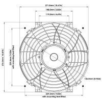
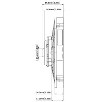
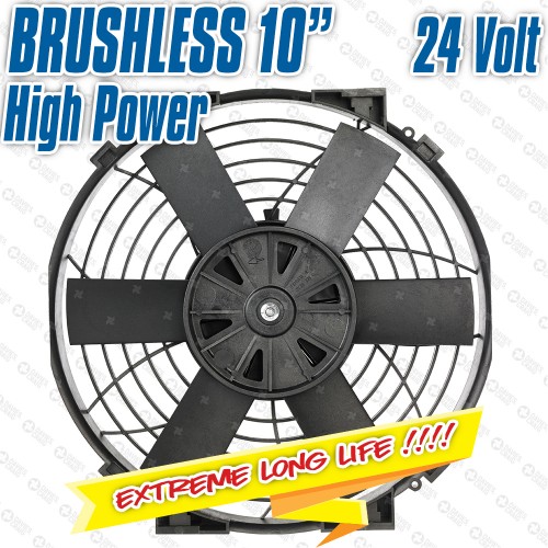
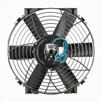
Brushless 10" High Power Thermatic® Electric Fan (24V) (#0126)
AUD 335.00
(Ex. GST)
Add to Cart
View Product
12" Thermatic® Electric Fan (12V) (#0162)
AUD 120.75
(Ex. GST)
Add to Cart
View Product
12" Thermatic® Electric Fan (24V) (#0163)
AUD 133.35
(Ex. GST)
Add to Cart
View Product
Brushless 12" High Power Thermatic® Electric Fan (12V) (#0127)
AUD 345.00
(Ex. GST)
Add to Cart
View Product
Featured
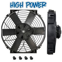
12" High Power Thermatic® Electric Fan (12V) (#0155)
AUD 173.00
(Ex. GST)
Add to Cart
View Product
Featured
12" High Power Thermatic® Electric Fan (24V) (#0156)
AUD 173.00
(Ex. GST)
Add to Cart
View Product
Brushless 12" High Power Thermatic® Electric Fan (24V) (#0128)
AUD 345.00
(Ex. GST)
Add to Cart
View Product
14" Slimline Thermatic® Electric Fan (12V) (#0164)
AUD 145.95
(Ex. GST)
Add to Cart
View Product
14" Slimline Thermatic® Electric Fan (24V) (#0165)
AUD 159.60
(Ex. GST)
Add to Cart
View Product
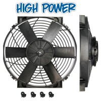
14" High Power Thermatic® Electric Fan (12V) (#0107)
AUD 189.00
(Ex. GST)
Add to Cart
View Product
14" Hi-Power Thermatic® Electric Fan (24V) (#0108)
AUD 207.90
(Ex. GST)
Add to Cart
View Product
«
1
2
3
4
5
6
7
8
9
10
»
Show:
20
40
60
80
All
Newsletter
Subscribe to our newsletter
Receive relevant news in your inbox!
SUBSCRIBE